We have built cAno2 based on the excellent MSP430FR5994. Designed for long term data collection in the big outdoors, it has BLE to allow easy configuration. An outline specification listing can be found below.
The 256KB of FRAM on the MSP430FR5994 can be shared between the data and program, storing to SD card or using one of the several communication options. cAno2 has onboard support for XBee, both the surface mount and through hole pinouts.
8KB of SRAM is available, with 4KB shared with the “Low Energy Accelerator”
Additional header boards have been made that carry LoRa or 2G-4G modems allowing for data transmission. These are connected via the 40 pin connector. An XBee header is directly available, both through hole and SMT variants.
BLE is available to enhance configuration over our original design. It can be used as the main communication path, however you may find “micro_cAno” or other boards on the market more suited to BLE only applications.
The BLE can also be used in pass-through providing a UART like interface for verbose development/deployment status.
The multiple Serial ports provide the option to easily interface to several modems, either for redundancy, or to use cAno2 as a data aggregator to collect mesh device data then forward the collated data to the cloud.
We mapped the GPIO to 40 pin connector, compatible with that of the Raspberry PI because we want to use the PiPaRus, mentioned in our earlier blog, however it also gives access to many other header cards.
| MCU | MSP430FR5994 256KB FRAM, 8KSRAM |
| 4xUART (BLE, XBee,GPS,Header) | |
| 1xI2C(9DOF,TPH,Header) | |
| 1xSPI(SD) | (SD socket on rear) |
| 2xSPI/I2C(Header,Header) | Can be configured as I2C master or slave |
| BLE (external power switch) | RN4871 Jumper UART connection for direct access to MSP BSL or UART. Alternatively for BLE access from an external USB2UART. |
| GPS (option) (external power switch) | Firefly X1 (optional battery backup) |
| XBee (option) (external power switch) | SMD & Through hole connector (on rear) |
| 9DOF (Accel/Magneto/Gyro) (option) | MPU-9250 (shared power switch*) |
| Temp/Pressure/Humidity (option) | BMP280 (shared power switch*) |
| Magnetic | SM351RT |
| 1xBlue LED | |
| 1xRedGreen LED | |
| 3v7-17V input Buck | 3v3 Out (fuse protected input) |
| 3V-3v6 Vin for MSP | Main power input for board |
| USB Micro for 5V input & LiIon charge | (on rear) |
| LiIon JST connector | (on rear) |
| LiIon charger | |
| 40 Pin connector | 2xSPI, 1xUART, 3v3, 3v7-17V, GPIO |
Specification, user guides and development resources for all modules can be found at the links above.
The Microchip Smart Data App (iOS, Android) can be used for application development on cAno2, setting the mode of the board. Various test scenarios are built into the default application, demonstrating all on-board capabilities.
Though currently untested it is expected cAno2 will be compatible with Energia which was used to run code on cAno.
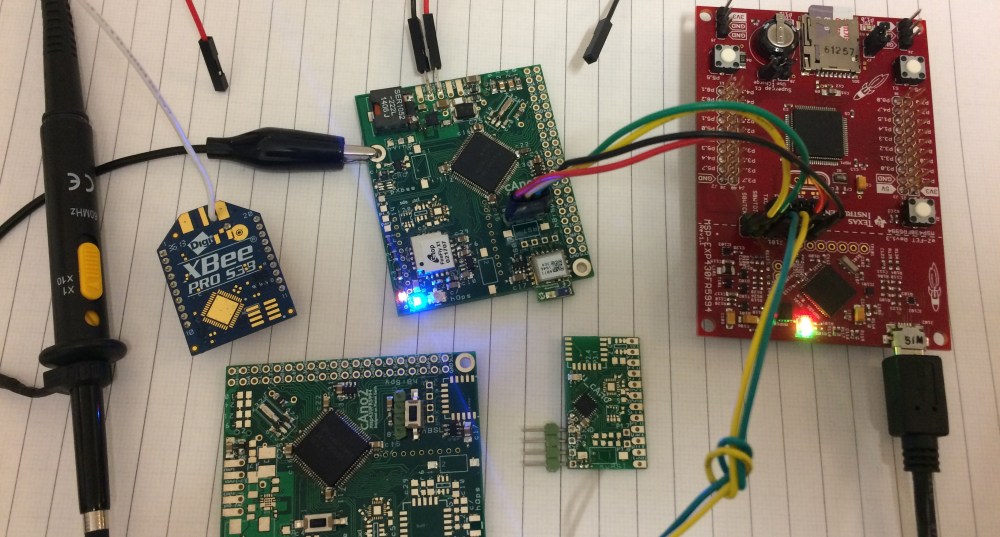
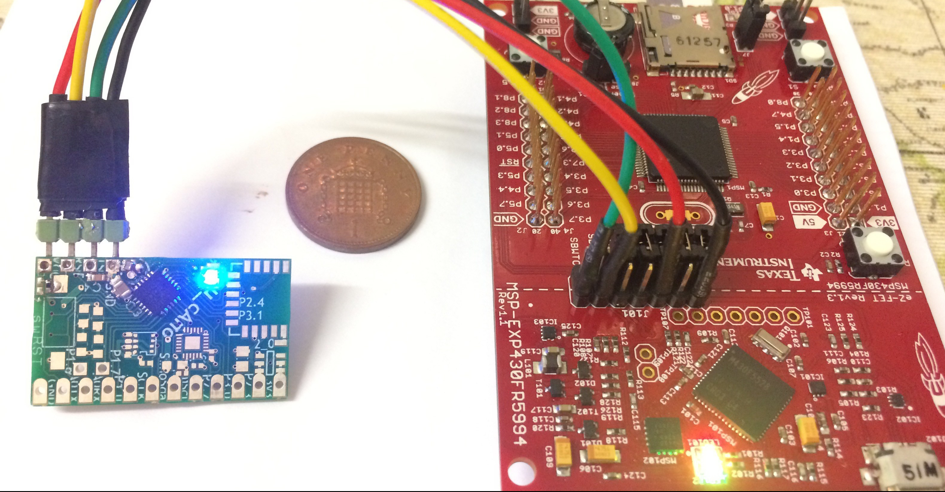
No onboard programming is available, cAno2 can be programmed and debugged using the MSP430FR5994 Launchpad available here. This also provides a USB UART interface, accessed via the 40-pin or BLE headers.
You can also see uCano in this picture, a MSP430FR2433 based board with the same BLE, 9DOF and BME280 options. More info coming soon, the MSP is up and running and its looking good.
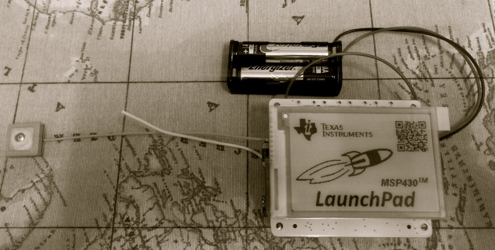
Demonstration of GPS streaming over BLE to an iPad. GPS cold starts in the region of 25 seconds and warm in 2 seconds.
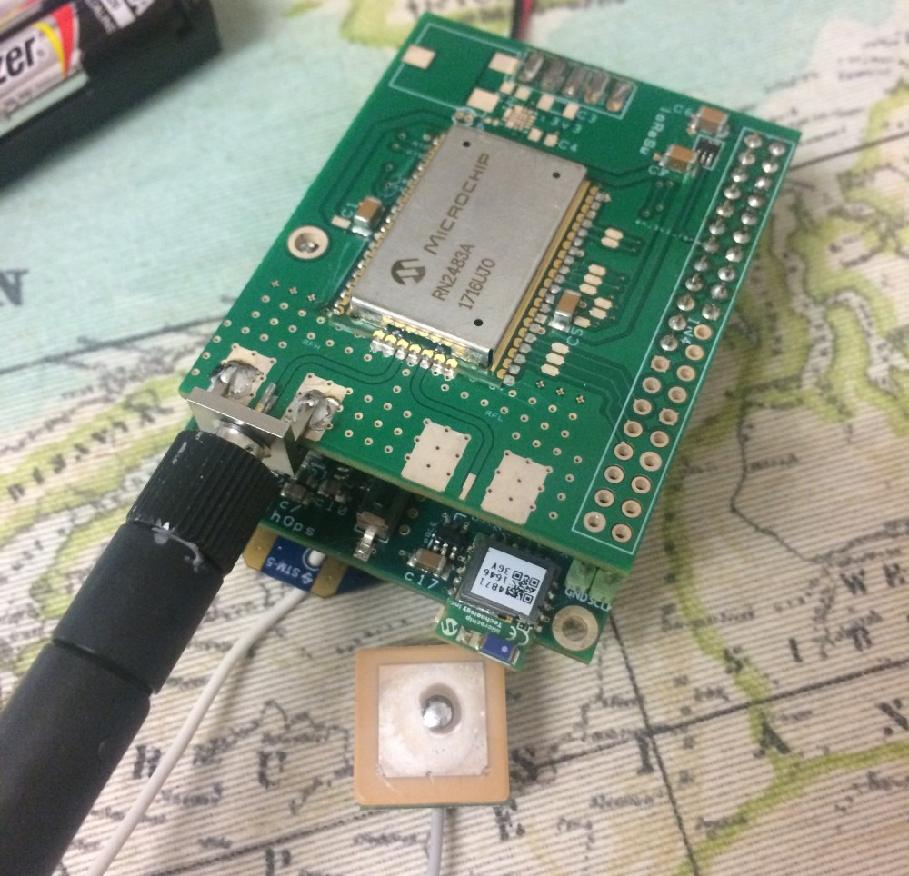
LoRa daughter board, based on the RN2483.
Running the Pervasive Display EPD demo on cAno2 using the PaPIRus Eink display.
cAno2 will be available soon.

One thought on “cAno2”